
Duty cycle: running time, starts per hour and why the limit differs by type
Duty cycle describes the proportion of time a compressor can run under load before it has to rest, expressed either as running time per hour or as a percentage of the hour. It is set by how the compressor deals with heat: the motor, the compression element and the oil or lubrication all warm up under continuous running, and each design has its own way of shedding that heat before something wears out or a thermal cutout trips.
Running time versus starts per hour
Two separate limits sit inside the same spec sheet. Running time per hour caps how long the compressor can stay on load once it starts, which matters most for a piston machine whose cylinder and valves heat up steadily the longer they work. Starts per hour caps how often the motor can switch on and off, which matters because every start draws a surge of current well above the running load, and a motor that starts too often heats its windings faster than it can cool between cycles. A workshop with a large air demand and a small receiver tends to hit the starts-per-hour limit before it hits the running-time limit, because the compressor keeps cutting in to refill a tank that empties quickly.
Why the limit differs by compressor type
A piston compressor is generally built for intermittent duty: it runs, fills the receiver, stops, and waits for pressure to drop before starting again, so its rating assumes rest between cycles. A rotary screw compressor is generally built to run continuously, loading and unloading, because its rotating element and oil circuit shed heat steadily. Scroll and vane compressors sit between the two: their moving parts run smoother than a piston but without the continuous cooling circuit of a screw element, so their duty cycle sits closer to the piston end of the range even though the mechanism is different.
Matching a compressor to the work means checking that its duty cycle covers your actual pattern of use. A distributor quoting on your job needs the running hours and the pattern of simultaneous use behind them, which is one of the figures worth sending when you get compressor quotes.
What happens inside a piston compressor on every stroke
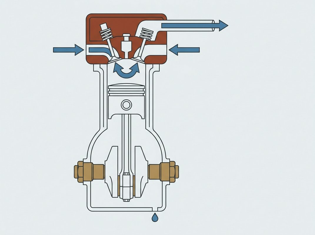
A piston compressor draws air into a cylinder as the piston moves down, then compresses it as the piston moves back up, pushing it out through a one-way valve once the pressure inside the cylinder exceeds the pressure in the line. The volume the piston sweeps on that stroke, before any of it is lost to valve timing or heat, is its displacement; what actually reaches the outlet, measured at atmospheric pressure and temperature, is always a smaller figure, because displacement and free air delivery are not the same number.
A single-stage compressor does the whole job in one cylinder: intake, compression to full working pressure, discharge. It suits lower working pressures, because compressing air that far in a single stroke raises its temperature sharply, and past a certain point the heat starts working against the compressor, making the air harder to seal and shortening the life of the lubricant and the valves.
A two-stage compressor splits the same job across two cylinders of different sizes. The larger, low-pressure cylinder takes air from atmospheric pressure up to an intermediate pressure, then it passes through an intercooler that brings its temperature back down before the smaller, high-pressure cylinder finishes the compression. Cooling the air between stages keeps the second compression closer to its starting temperature, which is why two-stage machines reach higher final pressures and tend to deliver more free air for a given power input than a single-stage machine of the same size.
Both designs rely on the same pair of valves per cylinder: an inlet valve that opens on the downstroke and a discharge valve that opens on the upstroke once cylinder pressure exceeds line pressure. It's the wear on these valves and rings, together with the heat generated on every stroke, that limits how long a piston compressor can run without a rest, a limit set by its duty cycle.
What happens inside a rotary screw element
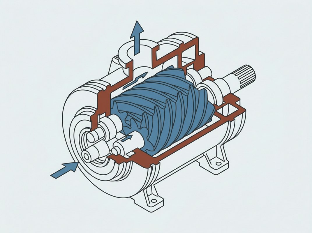
A rotary screw compressor compresses air between two meshing helical rotors, one convex (the male rotor) and one concave (the female rotor), turning in opposite directions inside a close-tolerance housing. Air drawn in at one end is trapped in the shrinking pocket between the rotors as they turn, and is pushed out at higher pressure at the other end. Because the rotors turn continuously, the air leaves in a steady stream.
That continuous action is what lets a rotary screw unit run under load for long stretches without the rest periods a piston compressor needs, which matters most where several tools or a spray line draw air more or less all day.
Oil-injected screw compressors
In an oil-injected rotary screw, oil is fed directly into the compression chamber as the rotors turn. The oil seals the small clearance between the two rotors, carries away the heat of compression, and lubricates the meshing surfaces, which allows the rotors to run at closer tolerances and higher pressure ratios than a dry set could tolerate. The oil is separated from the compressed air downstream, cooled, filtered and recirculated, and a residual trace still carries through to the outlet, which is why the air needs further treatment before it reaches anything sensitive to oil.
Oil-free screw compressors
An oil-free rotary screw keeps oil out of the compression chamber entirely. The two rotors are coated and precision-timed by external gears so they mesh without touching, and cooling is handled by air or water jackets around the housing. Building the rotors to this tolerance costs more than an oil-injected equivalent of the same output, and that cost buys air with no oil carryover to remove afterwards, which is the reason oil-free units turn up on food and pharmaceutical lines and on breathing air systems feeding a spray booth hood.
How a scroll or a vane compressor reaches working pressure
The scroll element
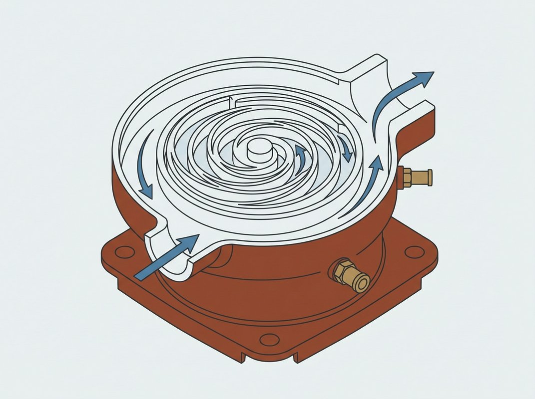
A scroll compressor uses two interleaved spirals, one fixed and one orbiting inside it without turning on its own axis. As the orbiting scroll moves, the pockets of air trapped between the two spirals shrink steadily and push the air toward the centre, where it leaves at working pressure. There is no valve opening and closing and nothing strikes anything else, which is why the mechanism runs smoothly and, in most scroll compressors, without any oil in the compression chamber at all.
That clean delivery is why scroll compressors turn up wherever the air itself has to stay clean: feeding a spray booth hood (see Breathing Air for Spray Booths), a dental surgery or a laboratory instrument. They tend to deliver less free air delivery (FAD) than a screw compressor of similar size, so a workshop with heavy simultaneous tool use will usually need something larger, but for a single low-demand line that runs intermittently and needs to stay quiet, a scroll unit does the job with little vibration (compressor placement and the noise limits that apply are covered in Compressor Noise: The Law, the Label and Where the Compressor Can Sit).
The vane element
A vane compressor holds a slotted rotor inside a cylindrical housing set off-centre from the rotor's own axis. Flat vanes slide in and out of the slots as the rotor turns, thrown outward to keep contact with the housing wall, and each pocket of air trapped between two vanes shrinks as it travels round to the outlet. Some vane compressors inject a small amount of oil to lubricate the sliding vanes and seal the pockets; others run dry.
The design gives a steady, low-pulsation flow, and the moving parts are simple enough that vane compressors turn up in mobile and vehicle-mounted equipment as well as fixed workshop lines. They suit continuous, moderate demand well: a line running long stretches at a fairly constant draw.
Whichever element sits inside the casing, a listing for a scroll or vane compressor still needs reading the same way as any other: the free air delivery (FAD) it can actually deliver at your working pressure. Displacement and Free Air Delivery works through that difference with the arithmetic shown.
Piston, screw, scroll or vane: how the types compare
Each row covers what the type is generally built for, so use it to shortlist a type before comparing individual models by their free air delivery (FAD) and displacement figures.
| Compressor type | Duty cycle | Noise | Oil-free option |
|---|---|---|---|
| Piston (reciprocating)Suits work with occasional bursts of high-pressure air | Built for intermittent running, with rest periods between cycles | Generally the loudest of the four, with output that pulses as each piston fires | Oil-free versions exist, mainly at the lighter end of the range |
| Rotary screwSuits workshops running air tools for most of the working day | Built for continuous running across a full shift without the same rest requirement | Quieter than piston output at a comparable delivery, usually enclosed in a cabinet | Oil-free screw elements are available where air quality matters |
| ScrollSuits lower-flow, quality-sensitive work such as a spray booth or a lab bench | Runs continuously at lower flow without the pulsing of a piston cycle | Among the quietest of the four, with fewer moving parts to generate vibration | Oil-free by design, with no oil in the compression chamber to begin with |
| Vane (rotary)Sits between piston and screw for continuous demand at moderate flow | Runs continuously with steady delivery | Moderate noise, generally closer to screw than to piston | Oil-free vane models are less common than oil-injected ones |
This reflects how each mechanism is generally built and used. Noise and duty cycle vary between individual machines, so check the maker's own figures before deciding.
Know the demand before you pick the type
The duty cycle and demand profile decide which type suits the work; the product listings show what is on offer once you know the figures.